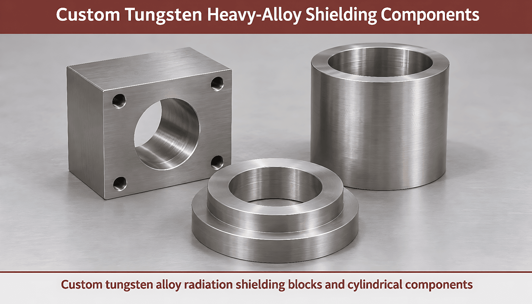
Tungsten Alloy Radiation Shielding: Grade Selection
Compare WNiFe, WNiCu, lead, and steel for photon-shielding components. Learn how density, photon energy, joints, magnetic response, and inspection…
Table of Contents
- Tungsten Alloy Radiation Shielding: What Controls Selection?
- Density, Photon Energy, and Shield Geometry
- Why Density Does Not Determine Thickness by Itself
- Joints, Penetrations, and Potential Streaming Paths
- Comparison Table: WNiFe, WNiCu, Lead, and Steel
- Magnetic Response, Machinability, and Space Constraints
- Five Steps to Specify a Custom Shielding Component
- Specification Summary: Density, Geometry, and Verification
- Buyer FAQ: Grades, Tolerances, Orders, and Delivery
- Request a Quote for Custom Tungsten & Carbide Parts
Tungsten alloy radiation shielding provides compact X-ray and gamma-ray shielding when you select the grade and component geometry for the photon energy and required attenuation. WNiFe or WNiCu selection also depends on magnetic response, mechanical loading, joints, and inspection requirements; density alone cannot establish the required thickness.
Tungsten Alloy Radiation Shielding: What Controls Selection?
Consider WNiFe when you need a dense, machinable shielding component and ferromagnetic response is acceptable. Consider WNiCu when low magnetic response is important near sensitive equipment, subject to a defined magnetic acceptance test.
- Density
- Mass per unit volume, expressed here in grams per cubic centimeter, or g/cm³.
- Attenuation
- Reduction in radiation intensity as photons pass through material.
- Tungsten heavy alloy
- A material containing tungsten particles in a metallic binder, commonly nickel–iron in WNiFe or nickel–copper in WNiCu, consolidated through liquid-phase sintering.
Typical heavy-alloy density is approximately 17.0–18.5 g/cm³, subject to grade confirmation. Both alloy families contain nickel; WNiCu is distinct from tungsten–copper, or WCu.
Our WNiFe and WNiCu heavy alloys include drawing-based components for radiation shielding. Practical takeaway: select an alloy family against attenuation, magnetic, and mechanical requirements together.
Density, Photon Energy, and Shield Geometry
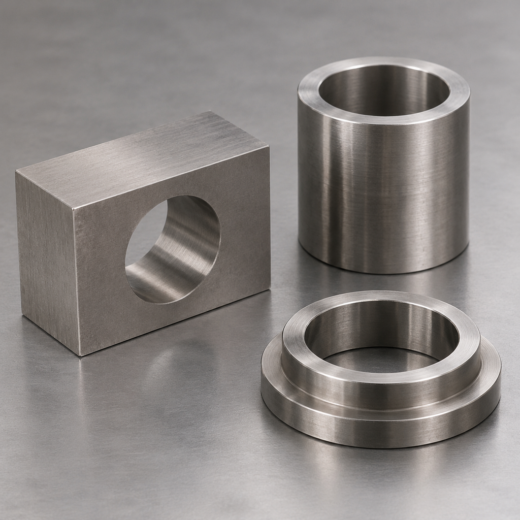
Required shielding thickness depends on the photon energy spectrum, source position, allowable transmitted radiation, and complete assembly geometry. For X-ray equipment, provide tube voltage, filtration, and operating conditions; for gamma sources, identify photon energies and source strength.
Specify source-to-shield and shield-to-evaluation-point distances, beam direction, exposure conditions, and the acceptance criterion. A bored block, sleeve, and enclosing housing can behave differently even when they contain equal metal mass.
Practical takeaway: provide the source and assembly conditions before requesting a shielding thickness.
Why Density Does Not Determine Thickness by Itself
Tungsten shielding density affects attenuation per unit thickness, but composition and photon energy also determine photon interactions. For a monoenergetic narrow beam, the uncollided intensity follows I/I₀ = exp[−(μ/ρ)ρx], where μ/ρ is the mass attenuation coefficient in cm²/g, ρ is density in g/cm³, and x is thickness in cm.
Real assemblies may require treatment of scattering, secondary radiation, and broad-beam buildup. Consequently, density ratios cannot establish a universal tungsten-to-lead or tungsten-to-steel thickness conversion.
Practical takeaway: use energy-dependent attenuation data and a calculation or test matched to the actual configuration.
Joints, Penetrations, and Potential Streaming Paths
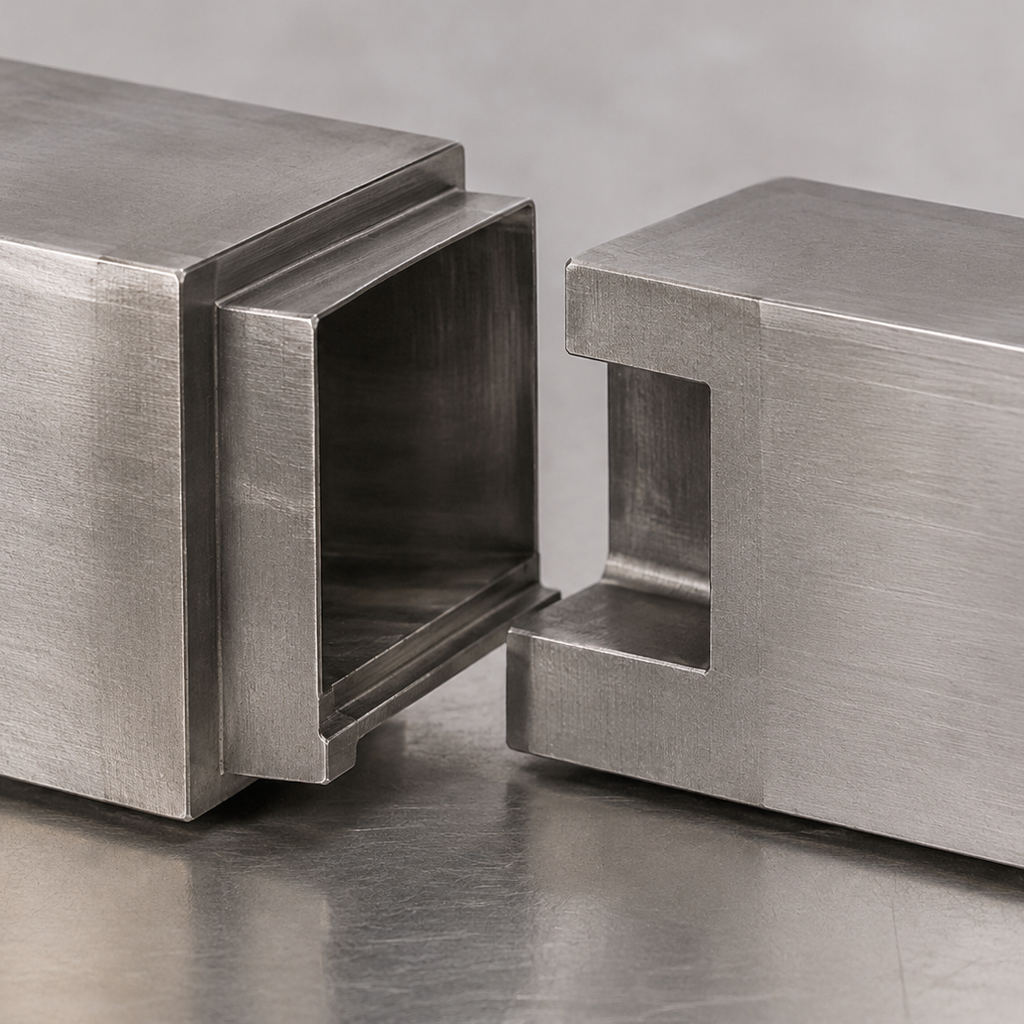
Joint clearances and penetrations can create streaming paths: routes through which photons encounter less shielding than intended. A thick wall does not compensate automatically for a direct path through a seam, cable opening, or mounting hole.
Evaluate stepped or overlapping joints in the actual source geometry. Specify minimum overlap, maximum assembled gap, bore diameter and position, minimum wall thickness, and locating datums; assess the worst permitted tolerance combination.
Practical takeaway: control the assembled radiation path, including fasteners and service openings, rather than relying only on nominal wall thickness.
Comparison Table: WNiFe, WNiCu, Lead, and Steel
WNiFe and WNiCu are candidates when shielding space is restricted and the component needs machined interfaces. Lead and steel remain useful alternatives where containment, structural support, available space, and fabrication requirements favor them.
| Material | Density, g/cm³ | Magnetic response | Selection considerations |
|---|---|---|---|
| WNiFe | Approximately 17.0–18.5, grade-dependent | Generally ferromagnetic | Compact shielding with useful strength and machinability; evaluate magnetic compatibility. |
| WNiCu | Within the approximate 17.0–18.5 heavy-alloy range; confirm composition | Generally selected for low magnetic response; verify | Useful near magnetically sensitive equipment; confirm mechanical properties. |
| Lead | Approximately 11.34 for pure lead | Nonferromagnetic | Soft and susceptible to creep; may require encapsulation and structural support. |
| Carbon steel | Approximately 7.85 | Generally ferromagnetic | Structural and fabrication advantages; typically requires more volume than tungsten heavy alloy for comparable photon attenuation. |
Nominal 90%, 95%, and 97% tungsten grades illustrate possible composition choices by weight; the balance contains binder metals. These examples are not interchangeable specifications or a statement that every composition is available in both families.
Practical takeaway: compare validated shielding envelopes, assembly mass, and fabrication cost for the same radiation conditions.
Magnetic Response, Machinability, and Space Constraints
WNiFe radiation shielding is a practical starting point when magnetic attraction is acceptable. For WNiCu shielding components, replace a vague “nonmagnetic” note with a measurable requirement, such as an agreed relative-permeability limit and test condition.
Heavy alloys can be machined into bores, threads, pockets, and locating surfaces, but deep features, thin sections, and restricted tool access affect feasibility and cost. Tighten tolerances where they control shielding continuity or assembly function.
Our comparison of WNiFe and WNiCu counterweights explains the separate mass-and-volume selection problem. Practical takeaway: specify shielding, mechanical fit, and magnetic acceptance independently.
Five Steps to Specify a Custom Shielding Component
A complete RFQ connects the shielding requirement to a manufacturable drawing and an agreed verification plan.
- Define radiation conditions. Supply photon energies or the X-ray spectrum, source strength or operating output, geometry, and allowable radiation at the evaluation point.
- Select the material envelope. Identify WNiFe or WNiCu, composition or grade designation, density acceptance limits, magnetic response, and mechanical loading.
- Release controlled geometry. Provide a revision-controlled drawing and, where useful, a 3D model. Identify minimum walls, overlaps, maximum gaps, bores, threads, datums, and surface finish.
- Agree verification. Define density testing, composition documentation, critical dimensional inspection, traceability, and any magnetic testing. Assign responsibility for assembly-level attenuation validation.
- Confirm commercial and shipping details. State prototype and production quantities, destination, required delivery date, packaging constraints, and documentation. Request separate manufacturing and transit estimates.
Our custom tungsten manufacturing capabilities support drawing-based review. Practical takeaway: resolve grade, geometry, and acceptance criteria before authorizing production.
Specification Summary: Density, Geometry, and Verification
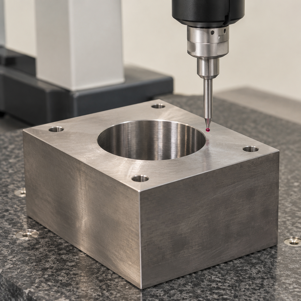
The specification should distinguish material acceptance from finished-component acceptance. A density result cannot verify bore position, and a dimensional report cannot establish attenuation performance.
| Item or component | Drawing or purchase-order requirement | Verification |
|---|---|---|
| Heavy-alloy material | WNiFe or WNiCu; confirmed composition; nominal density and acceptance range | Batch-linked material documentation and agreed density measurement |
| Bored shielding block | Minimum wall, bore diameter, position, and datum scheme | Critical-feature dimensional report |
| Cylindrical sleeve | Inner and outer diameters, wall minimum, length, and concentricity or runout as appropriate | Inspection against the specified geometric controls |
| Stepped ring or split housing | Minimum overlap and maximum assembled gap | Individual-part measurements and agreed assembly checks |
| Completed shielding assembly | Radiation conditions and attenuation acceptance criterion | Application-specific calculation and/or measurement |
Our tungsten component quality control covers density and dimensional inspection, batch records, and export packaging. Agree the required documents before ordering; no third-party certification is implied.
Key takeaways: confirm the grade, evaluate the complete radiation path, and verify critical features against the released drawing.
Buyer FAQ: Grades, Tolerances, Orders, and Delivery
The following answers identify what to confirm when purchasing prototype or production shielding parts. Final tolerances, order quantities, documentation, and delivery commitments depend on the reviewed specification.
Practical takeaway: a complete drawing and acceptance plan make quotations easier to compare and reduce unresolved requirements before production.
FAQ
Should I specify WNiFe or WNiCu for photon shielding?
Consider WNiFe when magnetic response is acceptable and mechanical performance matters. Consider WNiCu when low magnetic response is required. Confirm density, composition, mechanical properties, and any magnetic test requirement; neither family determines shielding thickness without the radiation and geometry inputs.
Which tolerances matter, and what tolerance capability is available?
Prioritize minimum walls, maximum joint gaps, minimum overlap, bore position, and assembly datums. No universal tolerance capability applies to every shielding part. We review achievable values against grade, dimensions, tool access, and inspection method; identify critical features on your drawing.
What determines MOQ and lead time for prototypes and production?
Minimum order quantity (MOQ) and lead time depend on grade availability, blank size, setup effort, geometry, finishing, inspection, and quantity. Request a prototype quotation and a separate production quotation. Confirm manufacturing lead time and transport time individually; no fixed MOQ or delivery interval is stated here.
Which certificates and inspection records can accompany a batch?
Request a batch material certificate identifying grade and composition, density results, and a dimensional inspection report linked to the drawing revision and lot. Confirm whether composition values are measured results or nominal grade declarations. Agree additional tests or third-party inspection before ordering; material documentation does not establish assembly shielding performance.
How should heavy shielding components be packaged and shipped to the United States?
Specify rigid blocking or fitted supports that prevent movement, separators between parts, and protection for bores, threads, edges, and finished surfaces. Use packaging rated for the shipment mass and handling loads, with moisture protection appropriate to the route. Agree lifting arrangements, gross weight, destination, transport mode, and applicable wood-packaging requirements before dispatch.