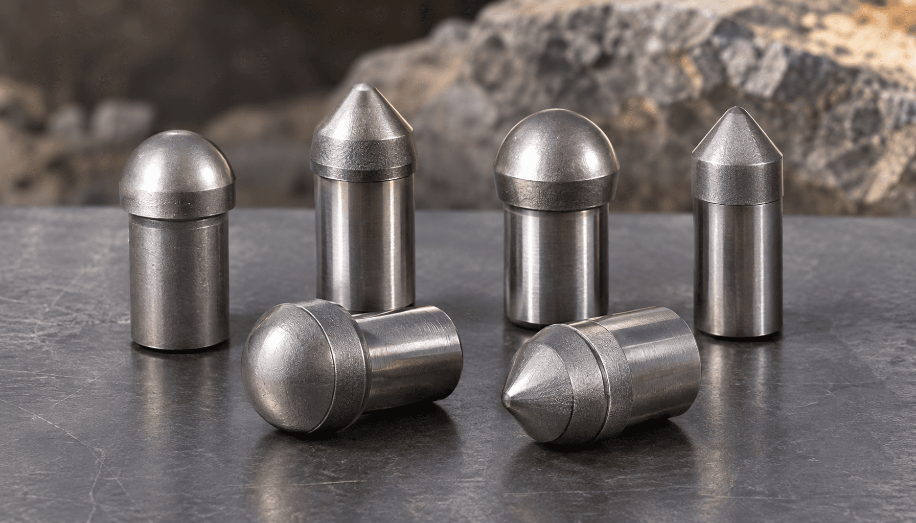
Rock Drilling Inserts: Carbide Grades for Impact
Use drilling-button failure patterns to evaluate WC grain size, cobalt binder, tip geometry, and mounting support. This guide explains grade comparisons…
Table of Contents
- Rock Drilling Inserts: Balance Wear Resistance and Toughness
- Read the Failure Pattern Before Changing the Grade
- Abrasive Flattening, Edge Chipping, and Bulk Fracture
- Separate Formation Effects from Mounting Problems
- Comparison Table: Grain Size, Binder, and Button Geometry
- Why Hardness Alone Does Not Predict Drilling Performance
- Five Steps to Select and Qualify a Drilling Insert
- Specification Summary: Grade Data, Dimensions, and Inspection
- Buyer FAQ: Grades, Fits, MOQ, Lead Time, and Shipping
- Request a Quote for Custom Tungsten & Carbide Parts
Select rock drilling inserts by identifying whether abrasive wear, edge chipping, or bulk fracture limits service life, then match the carbide grade, button profile, and mounting support to the drilling conditions. The hardest available grade can increase fracture risk when impact loading exceeds its toughness.
Rock Drilling Inserts: Balance Wear Resistance and Toughness
Rock hardness and abrasivity are different inputs. Hardness describes resistance to indentation or scratching; abrasivity describes how strongly the formation wears the tool. A quartz-rich formation can cause rapid wear, while joints, mixed layers, and interrupted contact can increase damaging impact loads.
For tungsten carbide drilling inserts, greater abrasion resistance must be balanced against resistance to crack initiation and growth. Rounded buttons generally provide more material behind the contact zone; sharper ballistic profiles concentrate contact pressure but require suitable formation conditions and support.
- WC grain size
- The characteristic size of tungsten carbide grains in the sintered material, normally reported in micrometers (µm).
- Cobalt binder percentage
- The cobalt mass fraction that binds the hard WC grains during sintering, the heat treatment that consolidates the compact.
- HRA
- Rockwell A hardness, an indentation measurement used for cemented carbide.
- Density
- Mass per unit volume, expressed in g/cm³; its expected value depends on composition.
Selection takeaway: Specify both the wear environment and the impact environment before comparing grades.
Read the Failure Pattern Before Changing the Grade
Start with used buttons, their positions on the bit, and operating records. Photograph working faces and fractures before cleaning removes deposits or handling damages the fracture surfaces.
Compare center and gauge buttons separately. Record drilling method, percussion settings, rotation, feed, flushing, formation changes, and service interval; the same grade can behave differently across these conditions.
Diagnostic takeaway: A grade change needs evidence of the failure mechanism and the conditions that produced it.
Abrasive Flattening, Edge Chipping, and Bulk Fracture
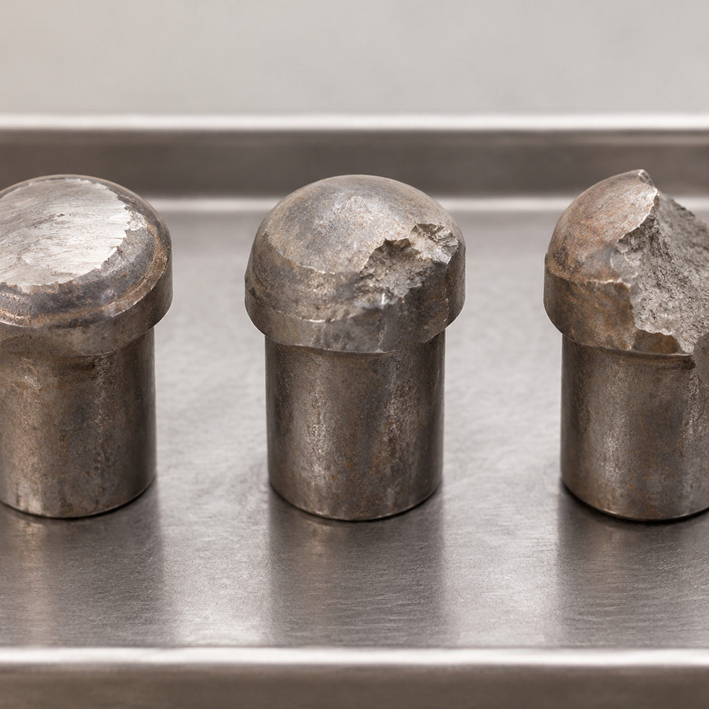
- Abrasive flattening: Broad, progressively polished wear flats suggest material removal dominates. Consider greater wear resistance after checking flushing and the permitted regrinding practice.
- Edge chipping: Local losses around the working profile suggest concentrated stresses. Review profile sharpness, impact conditions, grinding damage, and mounting support before increasing hardness.
- Bulk fracture: Large missing sections or cracks through the button require investigation of overload, installation damage, support, and material integrity.
These patterns can overlap. Surface appearance supports a diagnosis but does not establish the root cause by itself.
Practical takeaway: Classify the dominant damage before selecting a harder or tougher candidate.
Separate Formation Effects from Mounting Problems
Failures concentrated at one position or appearing immediately after assembly justify checking the pocket and installation process. Excessive interference can generate damaging assembly stresses; insufficient retention can permit movement, while unsuitable seating can leave the button poorly supported.
Define pocket diameter, engagement length, seating geometry, exposed height, and installation method alongside the insert dimensions. For carbide substrates for mining tools, the surrounding tool structure is part of the loading system.
Mounting takeaway: Resolve fit and support problems before attributing every fracture to insufficient carbide toughness.
Comparison Table: Grain Size, Binder, and Button Geometry
Compare rock drilling carbide grades using the supplier’s documented grain-size categories and actual grade properties. Fine, medium, and coarse are relative descriptions: their micrometer boundaries are not universal, and each category must be tied to a grade sheet.
| Variable | General behavior | Selection implication |
|---|---|---|
| Supplier-defined fine WC | Usually higher hardness at similar cobalt content | Screen for abrasion-dominated service; verify impact performance |
| Supplier-defined medium WC | Potential compromise between wear resistance and toughness | Evaluate as a balanced candidate using documented grade data |
| Supplier-defined coarse WC | Often greater toughness at similar cobalt content | Screen where impact damage dominates; assess wear loss |
| Higher cobalt content | Generally increases toughness and lowers hardness at comparable grain size | Evaluate against fracture frequency and abrasive wear |
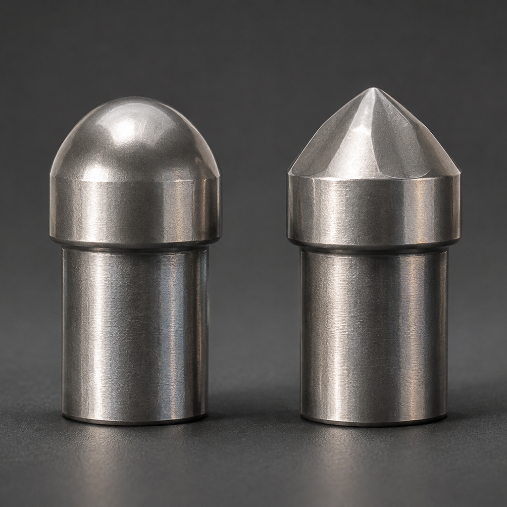
| Hemispherical button | Rounded working profile with substantial support behind contact | Common candidate for demanding impact conditions |
| Ballistic button | More pointed contact geometry | Evaluate penetration benefits against chipping and profile wear |
Comparison takeaway: Grain size, binder, and geometry must be evaluated together; none defines a universally best insert.
Why Hardness Alone Does Not Predict Drilling Performance
HRA measures indentation resistance, not resistance to repeated impact fracture. Grades with similar hardness can differ in grain distribution, binder structure, porosity, and crack resistance.
Request the grade designation, nominal cobalt content, WC grain-size specification, hardness range, and density range. Where mechanical-strength or toughness results are supplied, compare test methods before comparing numbers.
Grade-data takeaway: Use hardness to screen candidates, then qualify them under representative drilling conditions.
Five Steps to Select and Qualify a Drilling Insert
Qualify a candidate against your current insert using controlled assembly and comparable operating conditions.
- Document the baseline. Record formation, drilling method, operating settings, button positions, service life, and dominant failure.
- Shortlist grades and profiles. Match abrasion and impact demands to documented material properties and supported geometry.
- Freeze the drawing. Agree on shank dimensions, pocket fit, profile, exposed height, surface condition, and inspection methods.
- Run a controlled trial. Keep mounting and operating variables comparable. Record drilled distance, wear progression, penetration rate, and fractured or lost buttons.
- Approve the production specification. Set acceptance criteria, batch records, and change-control requirements before repeat purchasing.
Qualification takeaway: Approve the combination of grade, geometry, and assembly process demonstrated by the trial.
Specification Summary: Grade Data, Dimensions, and Inspection
The custom carbide manufacturing capabilities reference lists cobalt content of 3–20% and hardness of 85–93.5 HRA across the carbide portfolio. These documented ranges describe different materials; they are not a single drilling-grade specification or a recommendation to use either extreme.
| Item | Available reference or required specification | Acceptance basis |
|---|---|---|
| Cobalt binder | Portfolio range: 3–20% by mass | Confirm selected grade’s nominal value and limits |
| Hardness | Portfolio range: 85–93.5 HRA | Agree on grade-specific range and test method |
| WC grain size and density | Selected grade’s µm specification and g/cm³ range | Obtain grade data; no drilling-specific values are established here |
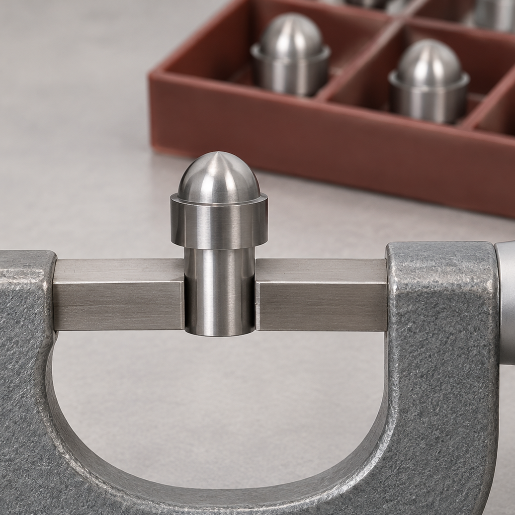
| Mounting geometry | Diameter limits, roundness, cylindricity, engagement length, and pocket limits | Approved drawing and agreed measurement method |
| Working profile | Tip radius or profile, overall length, exposed height, and surface condition | Drawing revision and inspection plan |
| Batch documentation | Material identification, hardness, density, and dimensional results | Traceable batch records agreed at order placement |
Specify dimensions in millimeters, with inch equivalents if needed. Diameter tolerance alone does not control roundness or cylindricity; require separate limits where fit depends on them. Achievable tolerances require review of size, geometry, grade, and finishing route.
Specification takeaway: Obtain the selected grade sheet and agree on the carbide batch inspection records before releasing the order.
Buyer FAQ: Grades, Fits, MOQ, Lead Time, and Shipping
Confirm commercial terms and acceptance requirements alongside the technical specification. The questions below cover the main purchasing decisions for custom mining inserts.
Key takeaways: Diagnose the failure, verify mounting support, compare documented grades, and qualify the complete assembly. For broader material-selection guidance, use the Tungstenmetal materials blog.
FAQ
Which grade and button shape should I choose for abrasive rock and high impact?
For abrasive service with stable loading, screen grades offering greater wear resistance. Where chipping or fracture dominates, investigate tougher candidates and rounded profiles after checking support and operating conditions. Select from documented WC grain size, cobalt content, and mechanical properties, then confirm performance in a representative trial.
Which dimensions and mounting-fit tolerances should the drawing define?
Define insert diameter limits, roundness, cylindricity, engagement length, overall length, tip profile, and exposed height. Specify the mating pocket dimensions and installation method so the intended interference can be reviewed. Tolerance capability is confirmed after drawing and finishing review; there is no universal fit suitable for every drilling button.
What determines MOQ and lead time for qualification orders?
Minimum order quantity (MOQ) and lead time depend on available tooling, grade preparation, geometry, sintering schedules, grinding, inspection, and order quantity. Identify trial quantities separately from forecast production volumes. We confirm feasibility, MOQ, and production lead time during quotation; transit time and any tooling work should be stated separately.
Which certificates and inspection records should accompany a batch?
Request batch material identification, the agreed grade specification, hardness and density results, dimensional inspection results, and traceability to the shipment. Specify whether composition verification or additional testing is required. Agree on document scope and sampling before ordering; a batch material certificate does not establish third-party management-system certification.
How should carbide button inserts be packaged and shipped?
Specify individual cells, trays, or dividers that prevent carbide-to-carbide contact, with cushioning and restraint to protect tips and ground mounting surfaces. Require grade and batch labels and protected export cartons or crates suited to shipment weight. Confirm destination, transport mode, delivery terms, freight responsibility, and required import documents in the quotation.