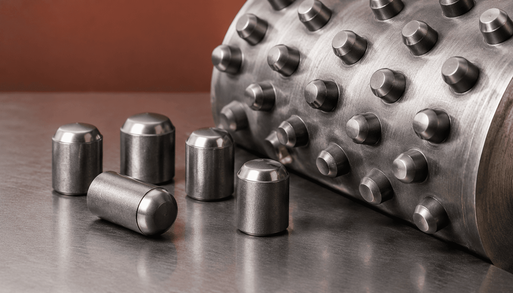
HPGR Carbide Studs: Grade Selection and Failure Modes
A practical guide to selecting HPGR stud grades, interpreting wear and fracture, defining mounting fits, and planning qualification orders with traceable…
Table of Contents
- How to Select HPGR Carbide Studs
- Define HPGR, WC Grain Size, Binder Content, and HRA
- Comparison Table: Grade Choices for Abrasion and Impact
- Read the Failure Evidence Before Changing Grades
- Progressive Wear, Fracture, and Stud Pullout
- Specification Summary: Grade, Geometry, and Mounting Fit
- Define Stud and Pocket Requirements as a Matched System
- Five Steps to Plan a Controlled Stud Trial
- Buyer FAQ: Grades, Tolerances, Trial Orders, and Shipping
- Key Takeaways for HPGR Stud Selection
Select HPGR carbide studs for the combined abrasion, impact, and mounting conditions of the roll surface—not hardness alone. Start with evidence of progressive wear, fracture, or stud loss, then evaluate WC grain size, cobalt binder content, stud geometry, and installation requirements together.
How to Select HPGR Carbide Studs
The right starting grade depends on what is failing. Gradual crown loss suggests an abrasion problem; repeated chipping calls for an impact and stress review; missing studs require investigation of retention as well as material.
For carbide studs for HPGR rolls, describe feed mineralogy, maximum particle size, moisture, operating pressure, roll position, and the existing stud design. Include changes in feed or operating conditions around the onset of damage.
Practical takeaway: Define the dominant failure mechanism before asking for a harder or tougher replacement.
Define HPGR, WC Grain Size, Binder Content, and HRA
- HPGR
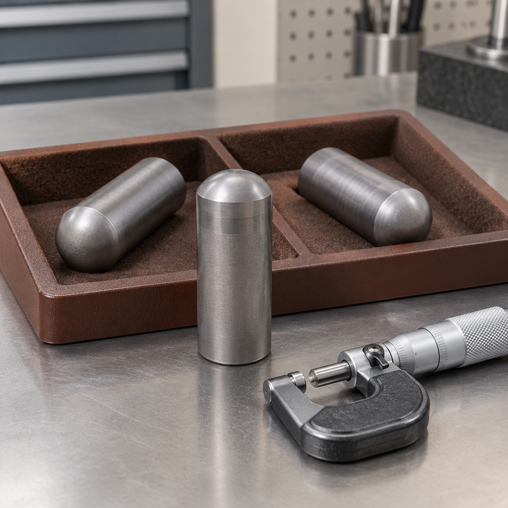
- High-pressure grinding rolls compress a particle bed between counter-rotating rolls. Studs protect the roll surface and help retain compacted material between them.
- WC grain size
- The characteristic size of tungsten carbide grains in the sintered material, normally reported in micrometers, or μm. Confirm whether the supplier reports the sintered microstructure or starting powder size.
- Cobalt binder content
- The mass percentage of cobalt binding the WC grains. For example, 90 WC–10 Co denotes 90 wt% WC and 10 wt% cobalt; it does not define a complete HPGR grade.
- HRA
- Rockwell A hardness, an indentation-hardness measurement. It indicates resistance to localized indentation, not fracture toughness.
Practical takeaway: Compare grain size, binder percentage, and HRA together—not a grade name or hardness value alone.
Comparison Table: Grade Choices for Abrasion and Impact
Finer WC and lower cobalt content generally favor hardness and abrasion resistance; coarser WC and higher cobalt content generally favor toughness. These are relative tendencies, not universal tungsten carbide stud grades or guaranteed service outcomes.
| Candidate direction | Expected tendency | Evidence supporting evaluation | Important limitation |
|---|---|---|---|
| Finer WC at similar cobalt content | Higher hardness and abrasion resistance | Progressive crown wear with little fracture | Impact tolerance may decrease |
| Lower cobalt at similar WC grain size | Higher hardness; less binder available for toughness | Abrasion-dominated loss | Greater chipping risk under unfavorable loading |
| Coarser WC or higher cobalt | Greater toughness, usually lower hardness | Repeated chipping after mounting and operating checks | Wear resistance may decrease |
| Retain the baseline grade | Isolates nonmaterial causes | Pullout, pocket damage, or localized installation failures | Does not resolve genuine grade mismatch |
For every candidate, obtain supplier-confirmed WC grain size in μm, cobalt wt%, HRA, and test methods. Review these alongside carbide grade and machining capabilities; do not treat broad portfolio ranges as HPGR recommendations.
Practical takeaway: Change one material variable where practical and verify the result in a controlled trial.
Read the Failure Evidence Before Changing Grades
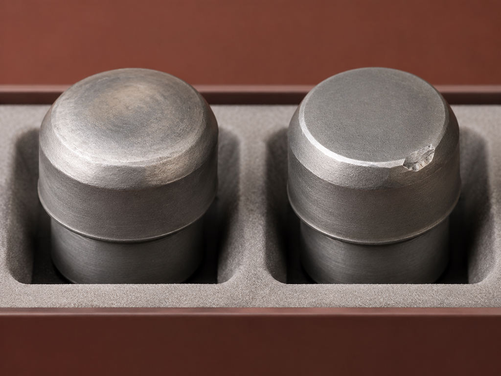
HPGR stud wear must be mapped by location and damage type before drawing conclusions about grade suitability. Photograph the roll surface before removal and identify edge, center, and clustered damage separately.
Preserve fractured pieces and nearby intact studs with their batch and position records. Compare crown loss, fracture origins, seating condition, pocket damage, and operating history; photographs alone rarely establish the root cause.
Practical takeaway: Preserve the assembly evidence, not just the failed carbide.
Progressive Wear, Fracture, and Stud Pullout
- Progressive wear: Smooth crown recession without major cracking supports an abrasion-led investigation. Compare wear rate at equivalent roll positions and processed tonnage; also examine retained material between studs.
- Fracture or chipping: Investigate impact loading, oversized feed, tramp material, crown geometry, excessive protrusion, installation damage, and pocket support before reducing hardness.
- Stud pullout: An empty pocket does not prove weak carbide. Check whether the stud escaped intact or fractured below the surface, then inspect fit, pocket condition, seating depth, and the specified retention system.
A harder grade will not correct inadequate retention, and a tougher grade will not eliminate unsupported loading.
Practical takeaway: Classify wear, fracture, and stud loss separately when comparing trial results.
Specification Summary: Grade, Geometry, and Mounting Fit
Specify custom carbide studs as finished components with an agreed material condition and inspection plan—not simply a nominal diameter and hardness.
| Item | Required specification | Acceptance evidence |
|---|---|---|
| WC–Co grade | Supplier grade code, cobalt wt%, WC grain size in μm, HRA range | Grade data and batch hardness results; composition and microstructure verification as agreed |
| Density | Grade-specific range in g/cm³; density means mass per unit volume | Batch test result and method |
| Stud geometry | Diameter, overall length, crown radius/profile, chamfers, and seating length | Drawing-linked dimensional report |
| Mounting interface | Stud and pocket limits, form tolerances, finish, and retention method | Fit review and inspection records |
| Surface and traceability | Agreed crack/chip criteria, lot identification, and reporting scope | Inspection disposition and package-to-lot traceability |
Review the scope of carbide batch inspection records before ordering. Density and hardness support quality control but do not independently prove fracture resistance or service suitability.
Practical takeaway: Tie every acceptance requirement to a drawing, test method, or agreed inspection record.
Define Stud and Pocket Requirements as a Matched System
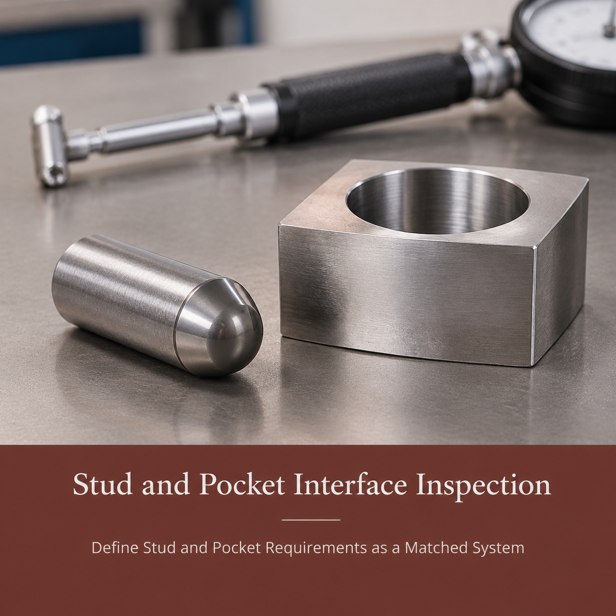
The roll designer must approve diameter limits, roundness, cylindricity, seating depth, protrusion, pocket condition, and installation procedure. A stud diameter tolerance alone cannot establish a reliable mounting fit.
For an interference-fit design, calculate the full tolerance stack. As a purely illustrative example, a stud measuring 16.000–16.010 mm and a pocket measuring 15.970–15.985 mm produce 0.015–0.040 mm diametral interference. These are arithmetic examples, not recommended HPGR dimensions or fit limits.
Account for assembly temperature, steel support, insertion alignment, and the approved retention method. Confirm machining capability after drawing review rather than assuming a universal tolerance.
Practical takeaway: Release stud and pocket requirements together under the roll designer’s approval.
Five Steps to Plan a Controlled Stud Trial
A useful trial separates material effects from installation and operating changes.
- Document the baseline. Record the current grade, geometry, roll position, feed conditions, operating settings, and failure distribution.
- Select a limited comparison. Test a documented candidate against the baseline, keeping geometry and mounting constant where feasible.
- Agree qualification documents. Define inspection sampling, batch identification, packaging, and acceptance criteria before manufacture.
- Control installation and exposure. Follow the approved installation procedure and compare equivalent roll positions over recorded operating periods.
- Evaluate separate outcomes. Track crown-height loss, chipped or fractured studs, pullout count, processed tonnage, and operating interruptions.
Use the custom carbide manufacturing workflow to identify tooling, sintering, grinding, and inspection milestones that affect the qualification schedule.
Practical takeaway: Agree pass/fail criteria before the trial starts; do not select a winner from appearance alone.
Buyer FAQ: Grades, Tolerances, Trial Orders, and Shipping
For high pressure grinding roll studs, confirm material, fit, qualification quantity, documentation, and delivery requirements before releasing the purchase order.
Practical takeaway: Make the answers below part of your RFQ and order review.
Key Takeaways for HPGR Stud Selection
- Diagnose progressive wear, fracture, and pullout as separate outcomes.
- Compare documented WC grain size, cobalt content, and hardness—not grade labels alone.
- Approve carbide geometry and the steel pocket as one mounting system.
- Qualify changes through controlled trials and traceable batch records.
Bottom line: The appropriate grade balances abrasion resistance with the toughness and support required by your actual operating conditions.
FAQ
How should I choose an HPGR stud grade?
Start with the dominant failure mode. For abrasion-led crown loss, evaluate a harder candidate; for repeated chipping, investigate loading and mounting before evaluating a tougher candidate. Obtain supplier-confirmed WC grain size, cobalt wt%, and HRA for both the baseline and trial grades.
Which dimensions and tolerances must the roll designer approve?
Agree stud diameter limits, length, crown profile, seating length, protrusion, form tolerances, and surface finish together with pocket dimensions and retention requirements. We confirm achievable tolerances after reviewing the drawing and inspection method; no blanket fit or tolerance applies to every roll.
What determines trial-order MOQ and lead time?
Minimum order quantity, or MOQ, depends on tooling availability, grade batching, geometry, and inspection scope. Lead time also depends on material availability, sintering schedules, grinding, qualification tests, and order quantity. Request a quotation that separates production time from shipping transit; trial quantities require case-by-case confirmation.
Which material records and certificates should accompany each batch?
Agree a batch material report identifying the grade and lot, hardness results and method, density results, and drawing-linked dimensional inspection. Specify whether cobalt analysis, WC grain-size verification, or independent testing is required. A supplier material report is not independent certification; confirm the required documents before ordering.
How should carbide studs be packed and shipped to a US destination?
Specify individual cells, sleeves, or rigid dividers that prevent carbide-to-carbide contact, with cushioning that prevents movement. Separate lots, identify quantities and drawing revisions, and use reinforced outer packaging appropriate to shipment weight. Confirm delivery terms, freight mode, consignee and importer details, and commercial invoice and packing-list requirements before dispatch.